Breakdown 2 of 4
Houdini PDG and the stud algorithm
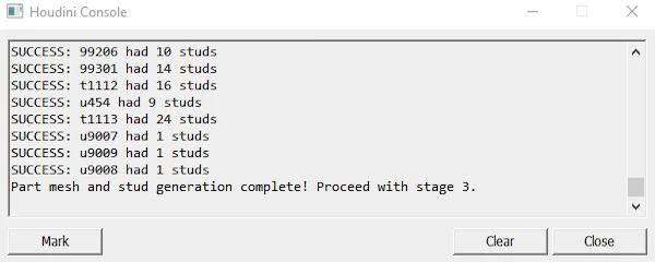
One PDG network builds all 945 parts with Stefan Müller's LDraw2Houdini, then my stud algorithm raycasts each one to find where other bricks connect.
Overview
The Houdini side has two jobs: generating a mesh for every part in the part list, and working out where each part can connect to another. The first is mostly Stefan Müller’s LDraw2Houdini (Müller, 2023). The second is my own work.
I left stud generation until last on purpose, since the tool already worked with studs set by hand on one test brick. Both jobs run in one PDG network, which suits working through a large set of parts.
Generating the meshes
LDraw2Houdini is a digital asset that parses the LDraw .dat files and builds the part
geometry, which saved me writing my own parser. My mesh branch uses it mostly as it
comes, plus scaling, a grid-aligned origin and UVs.
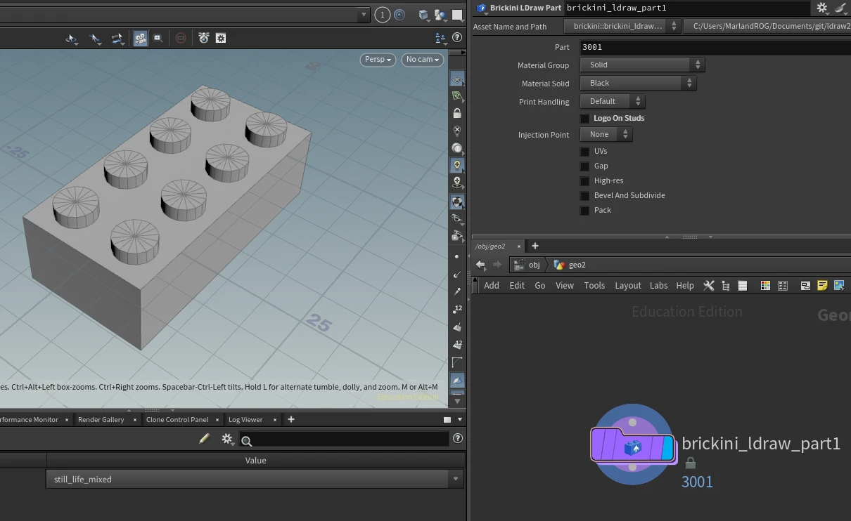
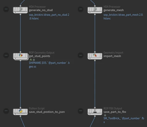
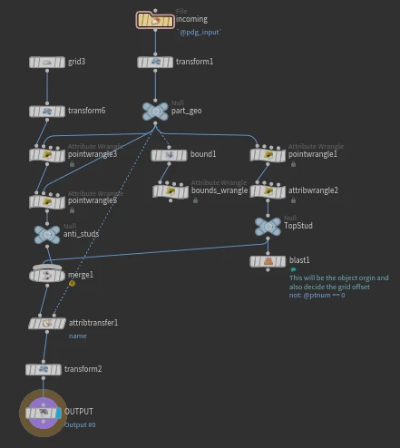
My first mesh generation wasn’t in PDG at all, and I only moved it over once the stud work started. The network makes one work item per entry in the part list, then splits in two. The right branch runs LDraw2Houdini’s full mesh asset through an HDA Processor and writes each part out as an FBX, and the left branch generates the stud positions.
Three unit systems
Before any of the stud work could line up, LDraw, Houdini and Unreal had to agree on size. LEGO’s grid isn’t uniform. A 1 x 1 brick is taller than it is wide, and a lot of building happens in plates, which are a third of a brick high (Shenoy, 2022).
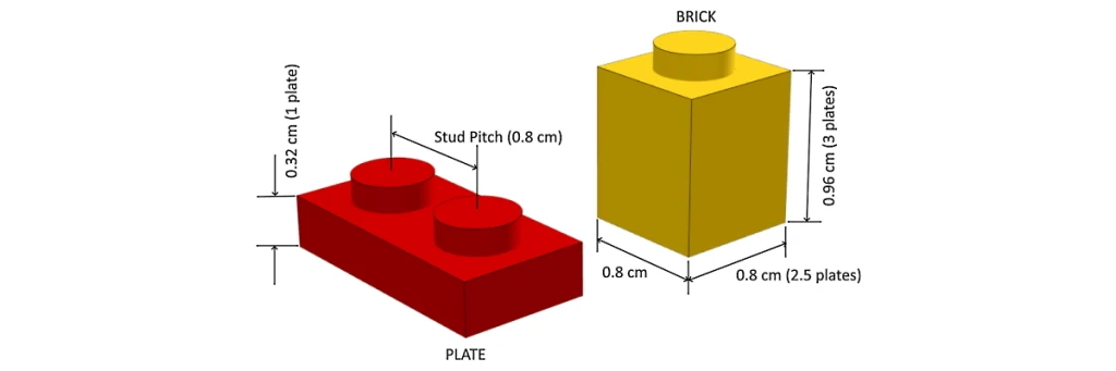
I scaled everything up by 10 into Unreal units (millimetres to centimetres), then by 1.25 so it sits on Unreal’s own grid values, for a scale factor of 12.5 overall. A 1 x 1 brick ends up 10cm x 10cm x 12cm and a plate 4cm, so the snapping grid in Unreal is 10 x 10 x 4.
In Houdini the part still comes in at real size, where a plate is 3.2 units tall. That’s the number in the code below. The last node in the stud branch scales the points and the mesh by 1.25.
Finding the top studs
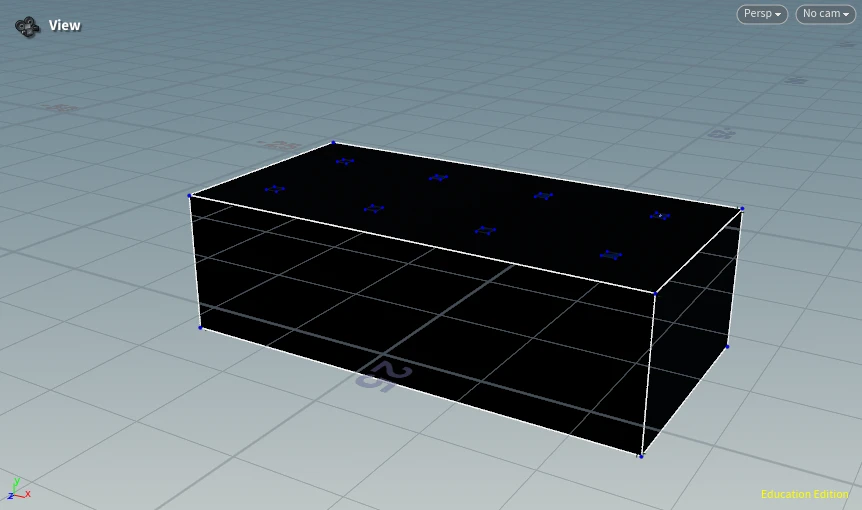
Finding the top studs is the simpler half. LDraw uses the same
primitive for a top stud every time, and LDraw2Houdini keeps those positions in its
cached version of a part before it adds the stud geometry, so I hijack that cache. The
stud branch keeps the points marked as studs, averages each cluster into one point per
stud and types it as SolidTopStud or HollowTopStud.
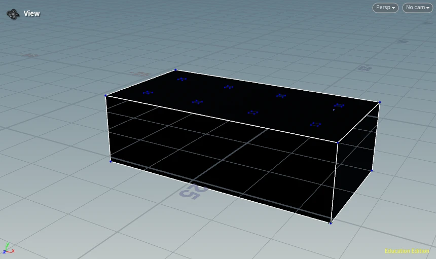
The first top stud then becomes the part’s origin. The geometry is moved so that stud sits at 0,0, and every part lines up with the grid the same way in the engine.
Finding the anti-studs
Anti-studs, where another part’s studs fit underneath, are harder, because they have to be found from the shape of the part itself.
My plan in October was to fire a ray up into the part from a random point underneath, then four rays sideways to check it was enclosed, counting three hits out of four as a valid position. The version I released keeps that idea but changes the details:
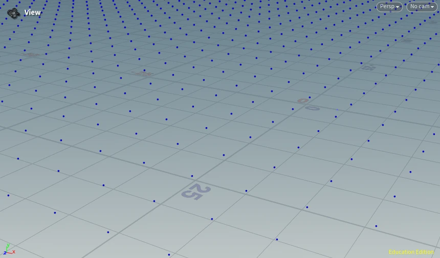
- A grid under the part. Points one brick apart, covering its bounds, with the first point at 0,0 so it lines up with the first top stud.
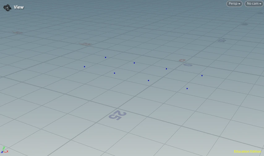
- Raycast up. Any point whose ray misses the part is deleted.
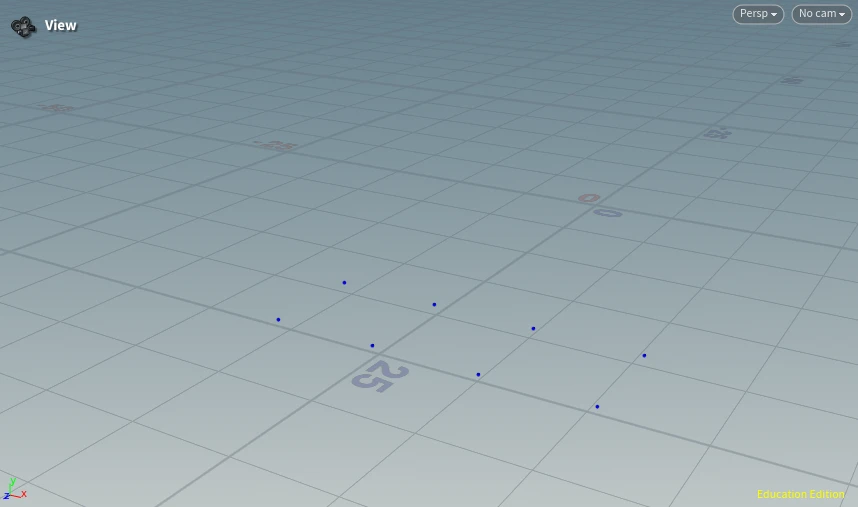
- Climb in plates. From the bottom of the part, step up one plate height at a time and fire eight rays outward. If six of the eight hit, a stud could sit there, so it’s a valid anti-stud.
- Clean up. A point that reaches the top without passing is deleted.
Step 3 is where most of the work happens. This is the wrangle as I released it:
// 8 directions: 4 cardinal + 4 diagonals
vector dirs[] = {
    { 1, 0,  0},   // +X
    {-1, 0,  0},   // -X
    { 0, 0,  1},   // +Z
    { 0, 0, -1},   // -Z
    { 1, 0,  1},   // +X+Z
    { 1, 0, -1},   // +X-Z
    {-1, 0, -1},   // -X-Z
    {-1, 0,  1}    // -X+Z
};
float plate = 3.2; // Snap to plate heights

// Start and stop positions for iteraation snapped
float minY = floor(@P.y / plate) * plate; ;
float maxY = floor(detail(0, "hit_y", 0) / plate) * plate;
float testY = minY; // Iteration height
float foundY = -1e9; // If valid set to height

// Ray cast config
int required = 6; // x/8 amount of rays hit to count as valid space
float dist = 100.0; // Max check distance in directions

// Loop upwards in plate increments until we reach the hit height
for (; testY <= maxY + 1e-4; testY += plate) {
    int hitCount = 0;

    // Cast 8 dir check - ray is slight higher to stop grazing angle
    foreach (vector D; dirs) {
        vector origin = set(@P.x, testY + 0.1, @P.z);
        vector hitP;
        float u, v;

        int prim = intersect(1, origin, D * dist, hitP, u, v);
        // Hit mesh
        if (prim >= 0)
            hitCount++;}

    // If reaches theshold for valid snap, store the height
    if (hitCount >= required) {
        foundY = ceil(testY / plate) * plate; // Snap down
        break;}
}

// If it wasnt valid at any iteration, remove
if (foundY < -1e8){
    removepoint(0, @ptnum);
    return;}

// Set to anti stud height
@P.y = foundY;

s@type = "AntiStud";
Six out of eight is the same ratio as my original three out of four. The climb is the real change, since it means a part with a recess partway up still gets its anti-studs at the right height.
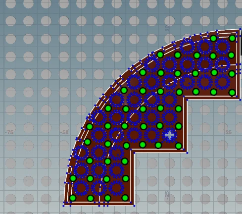
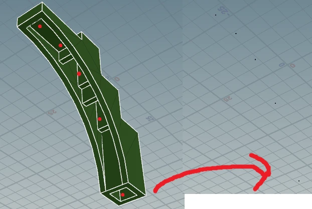
Besides the 2 x 4 brick, my other test mesh was part 58846, a large corner round brick with a cutout.
Writing it out for Unreal
Once both sets of points are merged, a Python Script TOP writes a JSON file per part with each stud’s type and its offset from the origin, swapping Y and Z on the way because Houdini is Y-up and Unreal is Z-up. Those files are merged back into the main part list, which the tool reads to spawn its snap handles.
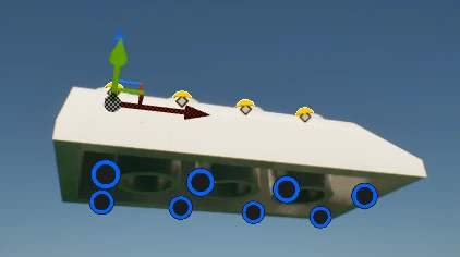
This is the 2 x 4 brick in the released list, cut down to one top stud and one anti-stud. The top studs sit 10 apart and the anti-studs 12 below them, which is one stud and one brick height in Unreal units:
{
  "PartID": "3001",
  "Name": "Brick  2 x  4",
  "Keywords": "brick;2;x;4",
  "Studs": [
    {
      "ID": 1,
      "Type": "SolidTopStud",
      "PosOffset": { "X": -10, "Y": 0, "Z": 0 },
      "RotOffset": { "Pitch": 0, "Yaw": 0, "Roll": 0 }
    },
    {
      "ID": 8,
      "Type": "AntiStud",
      "PosOffset": { "X": -30, "Y": 0, "Z": -12 },
      "RotOffset": { "Pitch": 0, "Yaw": 0, "Roll": 0 }
    }
  ]
}
Reflections
- Parts without top studs - Everything hangs off the first top stud, so a part without one (tiles, and a lot of curved and decorative pieces) has no origin on the grid, and the rays often miss its anti-studs too. That’s roughly a third of the library. Those parts sit off the grid, and moving them around means turning grid snapping off.
- False positives - The raycast test can pass positions that aren’t really anti-studs. The fix I’d try is checking whether the stud geometry actually fits closely against the walls it found.
- No side studs - The rotation offset is always zero. I’d like to add side studs, along with the more unusual stud formats.
- Baking the whole library up front - Adding one more part means cooking the whole lot again. With Houdini Engine inside the editor, an artist could request a part and have it generated without leaving Unreal.
Sources
Müller, S. (2023). ldraw2houdini: Import LDraw Files Directly into Houdini. [online] GitHub. Available at: https://github.com/stefanmuller/ldraw2houdini [Accessed 23 Nov. 2025].
Generates the part meshes, and its cache is where the top studs come from.
Shenoy, D. (2022). Isn't That Stud Supposed to Be on Top? No, It's SNOT - Building Sideways Using LEGO. [online] Brick Builder's Handbook. Available at: https://brickbuildershandbook.com/2022/01/20/ [Accessed 23 Nov. 2025].
The brick and plate dimensions.